void setup() {
  pinMode(LED_BUILTIN, OUTPUT);
}

void loop() {
  digitalWrite(LED_BUILTIN, HIGH);
  delay(1000);
  digitalWrite(LED_BUILTIN, LOW);
  delay(1000);
}
Mastering the Arduino Uno: A Comprehensive Guide

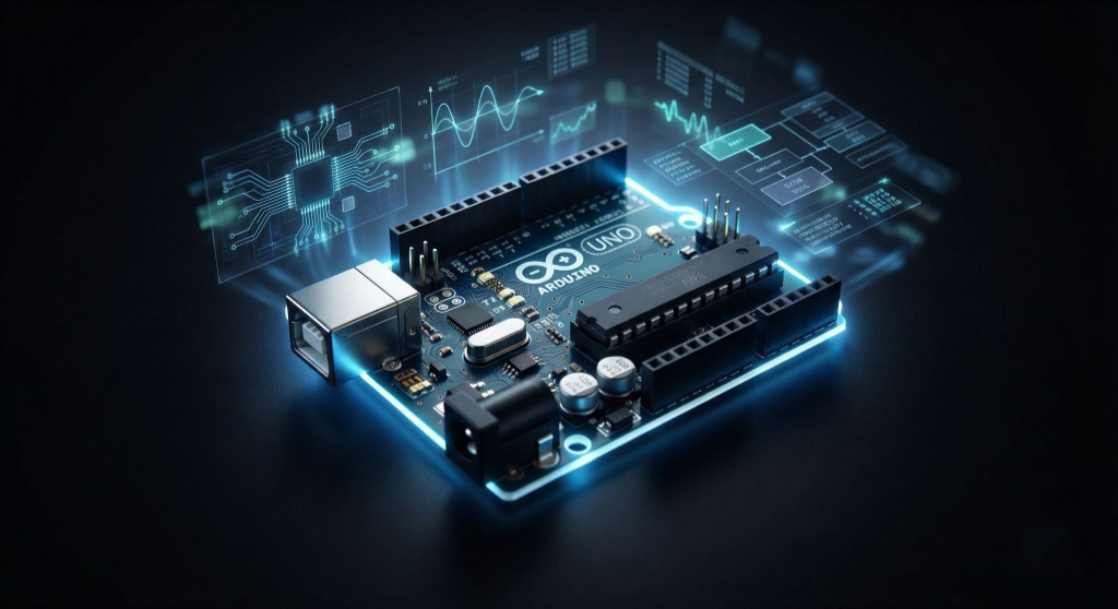
The Arduino Uno is arguably the most recognizable microcontroller board in the world. For hobbyists, students, and engineers alike, it serves as the definitive gateway into the world of electronics and programming. But what makes this little blue board so special? Why, after all these years, does it remain the gold standard for beginners? In this comprehensive guide, we'll dive deep into the Arduino Uno's architecture, its hardware specifications, and how you can master it to build everything from simple home automation systems to complex robotics.
Introduction to the Arduino Ecosystem
Arduino is an open-source electronics platform based on easy-to-use hardware and software. The 'Uno' in the name usually refers to the Arduino Uno R3, the third revision of the board. It bridges the critical gap between complex electronics engineering and creative coding, allowing anyone—regardless of background—to build interactive objects. The ecosystem thrives on its massive community, meaning if you can imagine a project, someone has likely shared code or a tutorial for it.
Hardware Specifications: Under the Hood
At the heart of the Arduino Uno is the ATmega328P microcontroller. While it may not compete with the raw processing power of a Raspberry Pi or modern PC, its real-time processing capabilities are perfect for hardware control. Understanding its specs is crucial for knowing the limits of your projects:
- Microcontroller: ATmega328P (8-bit AVR family)
- Operating Voltage: 5V
- Input Voltage (recommended): 7-12V
- Digital I/O Pins: 14 (of which 6 provide PWM output for simulating analog outputs)
- Analog Input Pins: 6 (10-bit resolution)
- DC Current per I/O Pin: 20 mA
- Flash Memory: 32 KB (ATmega328P) of which 0.5 KB used by bootloader
- SRAM: 2 KB (ATmega328P) - This is where your variables live during runtime
- EEPROM: 1 KB (ATmega328P) - Non-volatile memory for storing small amounts of data
Deep Dive: The Pinout
The headers bordering the board are your interface to the physical world. Let's break them down:
1. Power Pins: The board can be powered via USB or the DC barrel jack. The power pins include 3.3V and 5V outputs to power your sensors and modules. The GND pins are the common ground reference.
2. Analog Inputs (A0-A5): These pins are designed to read continuous voltage signals (0-5V). They use an internal Analog-to-Digital Converter (ADC) to translate voltage levels into a number between 0 and 1023. This is essential for reading temperature sensors, light sensors (LDRs), and potentiometers.
3. Digital I/O (0-13): These pins deal in absolutes: HIGH (5V) or LOW (0V). They can input data (detecting a button press) or output signals (turning on an LED). Note that pins 3, 5, 6, 9, 10, and 11 act as PWM (Pulse Width Modulation) pins, marked with a tilde (~), allowing for 'dimming' effects.
4. Communication Pins: Pins 0 (RX) and 1 (TX) are used for Serial communication. Be careful using these if you are also communicating with the computer via USB, as they share the same line.
Programming: The Arduino IDE
The hardware is useless without software. The Arduino Integrated Development Environment (IDE) is where you write your code, or 'sketches'. It uses a simplified version of C++, hiding much of the complexity of register manipulation.
Every Arduino sketch requires two fundamental functions:
- void setup() { ... }: This runs exactly once when the board is powered up or reset. It's used to initialize variables, pin modes, and start libraries.
- void loop() { ... }: This runs continuously after setup completes. It contains the main logic of your program, constantly monitoring inputs and controlling outputs.
Your First Project: The Basic Blink
The 'Hello World' of hardware is blinking an LED. The Uno has a handy built-in LED connected to pin 13, so you don't even need external components to test it.
Here is the logic: inside `setup`, you define pin 13 as an OUTPUT. Inside `loop`, you write a HIGH signal to the pin, wait for 1000 milliseconds (1 second), write a LOW signal, and wait again. This creates the blinking effect.
void setup() {
  // initialize digital pin LED_BUILTIN as an output.
  pinMode(LED_BUILTIN, OUTPUT);
}

// the loop function runs over and over again forever
void loop() {
  digitalWrite(LED_BUILTIN, HIGH);  // turn the LED on (HIGH is the voltage level)
  delay(1000);                      // wait for a second
  digitalWrite(LED_BUILTIN, LOW);   // turn the LED off by making the voltage LOW
  delay(1000);                      // wait for a second
}
Expanding Horizons: Shields and Modules
Once you master the basics, the true power of Arduino comes from 'Shields'—pre-built circuit boards that stack on top of the Uno to add specific capabilities. Need to connect to the internet? There's a WiFi shield. Want to drive high-power motors? Get a Motor Driver shield. This modularity allows for rapid prototyping.
Conclusion
The Arduino Uno is more than just a microcontroller; it's a tool for empowerment. It demystifies technology and puts the power of creation into your hands. Whether you are automating your garden, building a weather station, or designing a robot, the journey starts with this humble blue board.